-
در بخش Sell Offers، دسته بندی Audio and Video، Province Ilam موردی پیدا نشد.
دسته بندی Audio and Video را امتحان کنید.-
Telecom and SCADA between electrical substations and a study of the structure and how to communicate in DPLC DG CCHP, CHP
- Introduction: به because of the extensiveness of the network of interconnected production and transmission in the electricity industry and the scattering of the stations in the points, sometimes out of reach, launching and roughing telecommunication systems of the basic needs of the industry, the electricity industry. Land uses major telecommunication in the electric power industry include : 1 - the transfer of information and send commands auto-protective to isolate sections of injured and defective in the shortest time and avoid the extensiveness of the minor accidents to the entire network and the Prevention of possible accidents. 2 - transfer information collected from posts and power plants to centers of control and transfer commands to the control from control centers to the stations. 3 - coordination of operation and communicate between departments, staff and operational through the network, telephone, independent power. سیستم communication used in the network, telecom, power industry, included wireless, etc. microwave oven, ETC., PLC, ETC., DTS., the fiber optic system, and switching. - PLC system telecommunication is that of lines of high pressure at the frequency of 40 to 400 kHz for the transfer of messages, telecommunication uses. - DTS network dedicated Hot Line Telephone دیسپاچینگ can be. - cable OPGWدر power transmission lines, instead of the Earth Wire for data transfer with the volume and security of the most used. سیستمPower Line Carrier is one of the modern methods of data transfer, which is its acronym PLC, but not the controller logic programmable, but power transmission lines. توسعه resources, production, transmission and distribution of electrical energy need urgently to the existence of a network between key points power system, like the Centers of production, conversion, decision-making and distribution, mostly at intervals far apart, actually have been there. Transmission lines can be used to send the waves of frequency above the carrier information in the system of telecommunication used. System that for this species the transfer of information used in the tool, \\\"transmission carrier wave, the information on the system pressure, strong\\\" or PLC is called. موارد under the necessity of creating a network Telecommunications PLC to clear the track: 1 - network, telecom, public respond to the communication needs of the direction of the effective operation of the network, strong pressure is not. 2 - تبادلاطلاعات between the Centers of دیسپاچینگ and other پستهاتوسط a شبکهمخابراتی مطمئنو dedicated, from the necessities of such centers can be. 3 - use a comprehensive network of telecommunication, posts can to protective equipment equipped with a return that makes the ability to trust more and effective operation of the network can be. 4 - the lack of a network dedicated to. the weakness of communication via network, telecommunications, telecommunications company, the lack of access the majority of posts located outside the city, to the lines of communication PTT problems are that if there is a network, make sure the sides have to be exploited more efficiently from the network it creates. با pay attention to the tips above, the direction of Upland, the bugs listed and operation of the grid, can be used سیستمهایPLCچنین networks of Telecommunication for use in networks power supply design. استفاده from the PLC instead of other communication systems, such as cable, telephone, etc. radio waves and microwaves, and ... has benefits that can include : 1 - due to the insignificant being, the drop signal carries information in each area. the Centers of production and distribution of electrical energy, usually at intervals away from each other واقعند can be straight by Ka ...
Audio and Video Tehran -

Eurasia equipment supplier
eurasia equipment supplier\r\n\r\nEurasia equipment supply\r\n\r\nOur activity throughout Iran\r\n\r\nContinuous activity since 1992 in supplying raw materials, parts and equipment, industrial machinery and production lines from Europe and Asia.\r\n\r\nDesign supervision and supervision during construction and assembly and installation and commissioning of equipment, industrial machinery and workshop production lines, factories and industrial projects of various industries in the fields of electricity and electronics and industrial automation, thermal and refrigeration facilities, construction and production mechanics , mechanics of fluids and solids, mechatronics\r\n\r\n\r\nBachelor of purchasing, sales engineering and supply of parts and equipment, products and goods for laboratory, health and hospital consumption, raw materials for oil and refinery industries - gas - petrochemical - power plants - factories and industrial and mining workshops, construction, devices and machines , import and export production lines\r\n\r\n\r\nEurasia\'s equipment supply activity is 100% private and genuine and is not affiliated to any of the organs - institutions - organizations - banks - and other government centers.\r\n\r\nIf there is no response, please send your message via Telegram or WhatsApp\r\n\r\n\r\n97 545 545 - 0915 Chabahar Free Zone\r\n\r\n83 46 636 - 0916 Arvand Roud Free Zone\r\n\r\n59 34 424-0914 Aras and Mako Free Zone\r\n\r\n21 97 797 - 0917 Kish and Qeshm Island Free Zone
Audio and Video Tehran -
Grounding System Calculations with CYMEGRD, DEHN, CDEGS 17, DEHN, DIGSILENT2024 and CYMCAP Sales
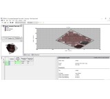
This company performs all grounding system calculations using software such as CymeGRD, ETAP, CYMCAP, CDEGS 17, PLSCADD V16.81, DIGSILENT2024, or DEHN. For purchasing DEHN, CDEGS, CYMGRD, CYMCAP, PLSCADD, or DIGSILENT2024 software, please contact 09126717215. The term CDEGS, which stands for Current Distribution, Electromagnetic Fields, Grounding and Soil Structure Analysis, is a powerful integrated software suite designed by sestech for precise analysis of various electromagnetic issues occurring in all industries including electrical networks. CDEGS software offers various advanced solvers for solving these problems: – Direct solutions of Maxwell's equations – Circuit-based analyses – Finite element methods – Inversion algorithms – Fourier analysis (FFT) – Transient analysis – Hybrid methods This software also supports all modes of electromagnetic coupling: – Conduction, through metallic elements, coatings, and the earth itself – Magnetic induction – Capacitive effects CDEGS software includes the following cores: RESAP: Soil Resistivity Analysis MALT: Low Frequency Grounding/Earthing Analysis TRALIN: Detailed Fault Current Distribution and EMI Analysis HIFREQ: Electromagnetic Fields Analysis FCDIST: Simplified Fault Current Distribution Analysis MALZ: Frequency Domain Grounding/Earthing Analysis SPLITS: Detailed Fault Current Distribution and EMI Analysis FFTSES: Automated Fast Fourier Transform Analysis The auxiliary tools included in this package are: Autotransient, CETU, FFT21Data, GraRep, GRServer, GRSplits, GRSplits-3D, ROWCAD, SESAmpacity, SESBat, SESCAD, SESConductorDatabase, SESConverter, SESCrossSection, SESCurveFit, SESeBundle, SESEnviroPlot SESFcdist, SESFFT, SESGSE, SESImpedance, SESLibrary, SESPlot, SESPlotViewer, SESResap, SESResultViewer, SESScript, SESShield, SESSystemViewer, SESThreshold, SESTralin, SICLCommand, SoilModelEditor, Given the vastness of the grounding system topic, terms such as Clean Earth, Dirty Earth, Floating Earth, Single Point Ground (SPG), Multi-Point Ground (MPG), TBB, TMGB, TGB, Star Bonding (STAR), Mesh Bonding (MESH), MBN, IBN, GPR, SRG ... are frequently repeated in engineering documents. Various software like ETAP, SGW, SDWorkstation, CDEGS, etc., are offered by different companies for grounding system design. Most grounding system design engineers are familiar with ETAP and CYMGRD software. Some issues with these software include: - Considering the entire grounding network as equipotential - Ignoring the reactive part of grounding system conductors Among these, only SES (Safe Engineering Services & technologies ltd) software professionally addresses grounding system design. Some unique capabilities of this software compared to others include: - Grounding system design at high frequencies - Optimal grounding system design for substations and power plants compared to other software - Grounding system design in soil with any number of layers (horizontal, vertical, spherical, cylindrical, with defined volume, etc.), used for special centers like dams - Fault current distribution analysis in the grounding network - Lightning strike state studies on transmission lines, telecom towers, wind turbines, nuclear power plants, etc. - Analysis of transmission and distribution line parameters, power cables, EMI and EMC - Optimal 3D lightning protection system design (line, substation, etc.) according to IEEE and IEC standards - Analysis of electromagnetic issues caused by transmission lines on adjacent facilities such as railways, oil and gas pipelines, etc. - Assessment of electromagnetic effects on the environment (corona, acoustic noise, radio noise) The SES software suite from Canada includes several software packages, with the CDEGS package (Current Distribution, Electromagnetic Fields, Grounding and Soil Structure Analysis) being the most prominent. The CDEGS software package consists of 8 modules: RESAP, MALT, MALZ, TRALIN, SPLITS, HIFREQ, FCDIST, FFTSES, or in other words, 12 software packages: AutoGround, MultiGround, MultiGround+, MultiGroundZ, MultiGroundZ+, MultiFields, MultiFields+, MultiFieldsPro, MultilLines, AutoGridPro, AutoGroundDesign, Right-Of-Way. Each software package is composed of several modules as per the table below: CYMGRD is a software for designing and analyzing grounding systems, created to assist engineers in optimizing new network designs and reinforcing existing networks of any shape. Advanced features in a graphical environment combined with efficient analysis algorithms make this software a powerful tool to help engineers develop technical and economical designs. This software enables the design of grounding for substations, power plants, factories, and buildings. The design can be for uniform and two-layer horizontal soils, calculating touch and step voltages according to IEEE standards. For grounding calculations of solar power plants, considering that panel structures are part of the grounding system, calculations differ somewhat from typical substation grounding. The software receives fault current magnitude and duration, soil resistivity, and body weight from the user and performs the following using soil, network, and diagram modules: 1- Soil Module Measures soil resistivity based on one or two-layer models. This module can plot measured and calculated resistivities and compute maximum virtual touch and step voltages according to standards. 2- Network Module Calculates current injected by each conductor element into the soil and determines soil surface potential using these currents. The grounding network can be defined as single conductor or a set of conductors connected in a square. Substation layouts can be drawn in 2D or 3D. Underground pipes and adjacent grounding networks can be considered to assess their impact on fault current and surface voltage. 3- Diagram Module Summarizes soil resistivity and surface potential analysis results on screen, using 2D and 3D color plots for better presentation. Key features of CYMGRD software: - Grounding system design for low frequencies (especially substation grounding design per IEEE 80-2000) - Support for IEEE 80 2000, IEEE 81 1983, and IEEE 837 2002 standards - Finite element analysis of grounding conductors and rods - Calculation of station ground resistance (Rg) and Ground Potential Rise (GPR) - Touch and surface potential analysis inside and outside the grid with color display - Step voltage analysis - Support for symmetrical or asymmetrical networks of any shape - Modeling of return and distinct electrodes - Calculation of maximum single-phase to ground fault current for a specified network - And more... CYMGRD Screenshot 1 CYMGRD Screenshot 2 CYMGRD The CYMGRD software is a substation grounding grid design and analysis program specially developed to help engineers optimize the design of new grids and reinforce existing grids, of any shape, by virtue of easy to use, built-in danger point evaluation facilities. User-friendly data entry, efficient analysis algorithms and powerful graphical facilities make the CYMGRD software an efficient tool that helps the engineer arrive at technically sound and economical designs. Program Features The use of the CYMGRD software allows for the rapid analysis of various design alternatives to choose an economical solution for any particular installation. The program conforms to IEEE 80™ 2000, IEEE 81™ 1983 and IEEE 837™ 2002. Analytical Capabilities - Finite element analysis of the ground grid conductors and rods - Computation of the station ground resistance (Rg) and the Ground Potential Rise (GPR) - Touch and surface potential analysis, inside and outside the grid perimeter, with color display in 2D or 3D representation - Step voltage analysis - Uniform or two-layer soil model from field measurements or user-defined values - Computation of reduction factor (Cs) - Library of the most common types of surface layer materials - Library of typical station soil resistivity values - Safety assessment calculations for maximum permissible touch and step voltages as per IEEE 80™ 2000 - Current Split Factor (SF) estimated from substation configuration data as per IEEE 80™ 2000 - Computation of the Decrement Factor (DF) from bus (X/R) ratio and shock duration data as per IEEE 80™ 2000 - DC component of asymmetrical fault current taken into account in the computations - Electrode analysis for the optimal sizing of conductors and rods based on the most common type of electrode material as per IEEE Std. 80-2000 and Std. 837-2002 - Supports symmetrical or asymmetrical grids of any shape - Arbitrarily located ground rods - Ability to model return electrodes and distinct electrodes - Ability to model concrete encased rods - Computation of maximum single phase to ground fault current for a specified grid The CYMGRD/AutoCAD® Interface module The CYMGRD / AutoCAD® Interface module allows the user to alternate between the AutoCAD® and the CYMGRD environments. This utility is not a substitute for AutoCAD®. In fact, AutoCAD® remains a firm software requirement for CADGRD, because it is AutoCAD® that will produce the necessary *.DXF or *.DWG file(s) that contain the pictorial description of the substation grid layout realized with the CYMGRD software. Simulation Results Management The charts functionality allows: - Graphical comparison of deduced soil model with field measurements, for model acceptance - Color-coding of the surface potential gradients based on user-defined thresholds for touch or surface potentials. Any area of the grid can be selected with the mouse for detailed calculations and danger point evaluation - Equipotential contours for surface potentials in either 2-D or 3-D plots, with facilities to examine the graphs from any desired viewing angle - Graphics of touch and step voltage variation along any straight line, with comparison to the safe values computed by the safety assessment module - Graphic indications on the 2-D grid layout of the area being analyzed for touch and step voltages, for easy identification of hazardous locations More info (open/close) Explanation of grounding design with DEHN: DEHNsupport Toolbox software is a planning tool for lightning protection systems offering various calculation options, from risk management to calculating air terminal rod lengths, separation distances, and grounding electrode lengths. DEHNsupport, a product of DEHNsupport company, provides easy and practical electronic planning and decision support for planners, lightning protection installers, and electricians. This significantly facilitates professional implementation of comprehensive lightning protection systems. DEHNsupport Toolbox has been expanded with another module and now also supports comprehensive internal lightning and electrical protection planning. The new DEHNselect SPD software module allows defining and selecting all internal lightning and electrical protection products. It provides a structured plan with a bill of materials and quick online access to all selected product documents such as data sheets and installation instructions. DEHN support toolbox consists of the following modules: DEHN Risk Tool (Risk Management) Module DEHN Distance Tool Module (Separation Distance Calculation) DEHN Air-Termination Tool (Air Terminal Rod Length Calculation) DEHN Grounding Tool (Ground Electrode Length Calculation) DEHNselect SPD Tool Module (Surge Protective Device Selection and Dimensioning Guide) 1- Register the design in the system and receive a dedicated user panel 2- Calculate short circuit in TN and TT networks considering distribution factors, X/R ratio, and other recommendations in IEEE80 standard 3- Interpret soil resistivity in multilayer soils and determine apparent resistivity and effective depth 4- Grounding system calculations including resistance, GPR graph, step voltage, touch voltage, protective device trip time, and selection of trip curve and protective device 5- Select electrode and grounding conductor materials 6- Prepare official report in PDF format Tested download link for CYMGRD V.6.3.R7 software: https://s25.picofile.com/file/8455555850/CYMGRD_V_6_3_R7.rar.html Password: cyme Installation method: First, disable antivirus, then run the grd637 file. After installation, place the pk42mvdR.dll file in the software installation folder (usually not in the C drive). Then click on CYMGRD inside the installation folder to run the software. If no error message appears, the software is installed correctly. If an error about missing SC32W file appears, copy the contents of the REQUIRED FILE folder to the installation folder. This will resolve the issue. The following modules enable realistic and practical cable studies: Power Cable Ampacity Duct Bank Optimizer Module Multiple Duct Bank Module Short Circuit Rating Real Time Temperature Rating CYMCAP/MDB, Multiple Duct Banks module CYMCAP Software: CYMCAP software is used for precise calculation of the capacity and heat rating of power cables. Its accuracy increases confidence during cable upgrades and new cable designs. It also enhances system reliability and supports proper use of installed equipment. CYMCAP performs thermal capacity and temperature rise calculations for power cable installations. Determining the maximum current that power cables can carry without damaging their electrical properties is crucial for electrical facility design. This software was jointly developed by Ontario Hydro (Hydro One), McMaster University, and CYME International under the Canadian Electricity Association. Selecting the appropriate cable size is one of the most important engineering tasks, often done manually. If the chosen size is smaller than required, cable damage or system malfunction may occur; if larger, despite proper function, economic design considerations are neglected. In most projects, designers calculate cable size based on voltage drop and short circuit criteria, often ignoring thermal sizing. For thermal sizing, especially for MV and HV cables, cable construction and layer specifications must be accurately modeled, and allowable current calculated based on installation environments such as underground, air, tunnels, ducts, trenches, etc. In this course, using the professional cable sizing software CYMCAP, we introduce various cable aspects, steady-state sizing, transient sizing considering current profiles, temperature field estimation around cables, magnetic flux density calculation around cables, induced voltage on shields, optimizing cable arrangement in duct banks, cable impedance matrix calculation, etc., based on IEC60853, IEC 60287, and Neher-McGrath methods. For purchasing CYMCAP software, call 09126717215.
Audio and Video Tehran -
Sale of CYMGRD 8, CYMCAP, CDEGS, DIGSILENT 2024, DEHN TOOLBOX, ETAP2024, pvsyst8.06
Sale of XGSLAB10 with CYMEGRD8 and CDEGS - Sale of CYMEGRD8 and CDEGS17 and DIGSILENT2024 and DEHN CYMCAP ETAP2024 without limitation and with any number of users you want. If you wish to purchase CYMGRD8 or CYMCAP or CDEGS or PLSCADD or CDEGS 17 and DEHN SUPPORT or DIGSILENT 2024 ETAP2024 or XGSLAB or PVSYST 8.06, contact 09126717215. In this post, a free download link for CYMGRD 6.3 is provided for engineers and students. **This company performs all grounding system calculations with CymeGRD8, ETAP2024, CDEGS, and XGSLAB software.** CYMGRD is software for designing and analyzing grounding systems, created to assist engineers in optimizing new network designs and reinforcing existing networks (of any shape). Advanced features in the software's graphical environment along with efficient analysis algorithms make this software a powerful tool that helps engineers create technically and economically sound designs. If you wish to purchase CYMGRD8 or CDEGS17 or ETAP 20, contact 09126717215. The term CDEGS, which stands for Current Distribution, Electromagnetic Fields, Grounding and Soil Structure Analysis, is a powerful integrated software suite designed by sestech for precise analysis of various electromagnetic problems occurring in all industries including electrical networks. Among these, only the SES (Safe Engineering Services & Technologies Ltd) software professionally addresses grounding system design. Some unique capabilities of this software compared to others include: - High-frequency grounding system design - Optimal grounding system design for substations and power plants compared to other software - Grounding system design in soil with any number of layers (horizontal, vertical, spherical, cylindrical, with defined volume, etc.), used for special centers like dams - Fault current distribution analysis in grounding networks - Studies of lightning strike scenarios to transmission lines, telecom towers, wind turbines, nuclear power plants, etc. - Analysis of transmission and distribution line parameters, power cables, EMI and EMC - Optimal 3D lightning protection system design (lines, substations, etc.) according to IEEE and IEC standards - Analysis of electromagnetic problems caused by transmission lines on adjacent facilities like railways, oil and gas pipelines, etc. - Assessment of electromagnetic effects on the environment (corona, acoustic noise, radio noise) The SES software suite from Canada includes several software packages, with the CDEGS package being the most prominent. The CDEGS software package consists of 8 modules: RESAP, MALT, MALZ, TRALIN, SPLITS, HIFREQ, FCDIST, FFTSES, or 12 software packages including AutoGround, MultiGround, MultiGround+, MultiGroundZ, MultiGroundZ+, MultiFields, MultiFields+, MultiFieldsPro, MultilLines, AutoGridPro, AutoGroundDesign, Right-Of-Way. CDEGS offers advanced solvers for the mentioned problems: - Direct solutions of Maxwell's equations - Circuit-based analyses - Finite element methods - Inversion algorithms - Fourier analysis (FFT) - Transient analysis - Hybrid methods It covers all electromagnetic coupling modes: - Conduction through metallic elements, coatings, and soil - Magnetic induction - Capacitive effects CDEGS includes the following cores: RESAP: Soil Resistivity Analysis MALT: Low Frequency Grounding/Earthing Analysis TRALIN: Detailed Fault Current Distribution and EMI Analysis HIFREQ: Electromagnetic Fields Analysis FCDIST: Simplified Fault Current Distribution Analysis MALZ: Frequency Domain Grounding/Earthing Analysis SPLITS: Detailed Fault Current Distribution and EMI Analysis FFTSES: Automated Fast Fourier Transform Analysis Supporting tools include Autotransient, CETU, FFT21Data, GraRep, GRServer, GRSplits, GRSplits-3D, ROWCAD, SESAmpacity, SESBat, SESCAD, SESConductorDatabase, SESConverter, SESCrossSection, SESCurveFit, SESeBundle, SESEnviroPlot, SESFcdist, SESFFT, SESGSE, SESImpedance, SESLibrary, SESPlot, SESPlotViewer, SESResap, SESResultViewer, SESScript, SESShield, SESSystemViewer, SESThreshold, SESTralin, SICLCommand, SoilModelEditor. Each software package consists of a combination of several modules as detailed in the table. This software enables the design of grounding for substations, power plants, factories, and buildings. The design can be for uniform or two-layer horizontal soils and calculates touch and step voltages according to IEEE standards. For grounding system calculations of solar power plants, considering that panel structures are part of the grounding system, calculations differ somewhat from typical substation grounding. ### This software receives fault current magnitude and duration, soil thickness, soil resistivity, and body weight from the user and performs the following operations using soil, network, and diagram modules: 1. **Soil Module** Measures soil resistivity based on one or two-layer models. This module can plot measured and calculated resistivity and compute maximum virtual touch and step voltages according to standards. 2. **Network Module** Calculates current released by each conductor into the soil and determines soil surface potential using these currents. The grounding network can be defined as a single conductor or a set of conductors connected in a square. Substation layout can be drawn in 2D or 3D. Underground pipes and adjacent grounding networks can also be considered to see their impact on fault current and surface voltage. 3. **Diagram Module** Summarizes soil resistivity and surface potential analysis results on the display and uses 2D and 3D colored shapes for better presentation. ### Key features of CYMGRD software: 1. Grounding system design for low frequencies (especially substation grounding design according to IEEE 80-2000) 2. Support for IEEE 80 2000, IEEE 81 1983, and IEEE 837 2002 standards 3. Finite element analysis of conductors and rods in grounding networks 4. Calculation of station ground resistance (Rg) and Ground Potential Rise (GPR) 5. Touch and surface potential analysis inside and outside the network with color display 6. Step voltage analysis 7. Support for symmetrical or asymmetrical networks of any shape 8. Modeling of return electrodes and distinct electrodes 9. Calculation of maximum single-phase to ground current for a specified network 10. ... CYMGRD Screenshot 1 CYMGRD Screenshot 2 CYMGRD software is a substation grounding grid design and analysis program specially developed to help engineers optimize new grids and reinforce existing grids of any shape, featuring easy-to-use built-in danger point evaluation tools. User-friendly data entry, efficient analysis algorithms, and powerful graphical tools make CYMGRD an effective tool for technically sound and economical designs. Program Features CYMGRD allows rapid analysis of various design alternatives to choose economical solutions for any installation. The program complies with IEEE 80™ 2000, IEEE 81™ 1983, and IEEE 837™ 2002. ### Analytical Capabilities - Finite element analysis of ground grid conductors and rods - Computation of station ground resistance (Rg) and Ground Potential Rise (GPR) - Touch and surface potential analysis inside and outside grid perimeter with 2D or 3D color display - Step voltage analysis - Uniform or two-layer soil model from field measurements or user-defined values - Computation of reduction factor (Cs) - Library of common surface layer materials - Library of typical station soil resistivity values - Safety assessment for maximum permissible touch and step voltages per IEEE 80™ 2000 - Current Split Factor (SF) estimated from substation configuration per IEEE 80™ 2000 - Decrement Factor (DF) from bus (X/R) ratio and shock duration per IEEE 80™ 2000 - DC component of asymmetrical fault current included - Electrode analysis for optimal sizing of conductors and rods per IEEE Std. 80-2000 and Std. 837-2002 - Supports symmetrical or asymmetrical grids of any shape - Arbitrarily located ground rods - Modeling of return and distinct electrodes - Modeling of concrete-encased rods - Computation of maximum single-phase to ground fault current The CYMGRD/AutoCAD® Interface module **Allows switching between AutoCAD® and CYMGRD environments.** This utility is not a substitute for AutoCAD®, which remains required to produce *.DXF or *.DWG files containing the substation grid layout. Simulation Results Management ### Chart features include: - Graphical comparison of soil model with field measurements - Color-coded surface potential gradients based on thresholds - Equipotential contours in 2D or 3D with adjustable viewing angles - Graphs of touch and step voltage variations along lines compared to safety values - Graphic indication of analyzed areas on 2D grid layout More info (open/close) DEHN Earthing Tool software calculates the required length of grounding electrodes according to IEC 62305-3 standard based on electrode types A and B and foundation electrodes. Soil resistivity is a key factor in determining electrode length. To purchase DEHN, call 09126717215. ### Training Topics: ◄ **Necessity of grounding system ◄ Soil characterization ◄ Conductors and Rods tabs ◄ Settings for grounding system calculation ◄ Performing grounding system calculations ◄ Optimizing number of conductors and rods ◄ FEM method review ◄ IEEE method review** **Grounding design with GSD**: An online software for static grounding system calculations providing step-by-step simple design for electrical engineers. Calculation methods are based on formulas and relations recommended in BS 7430 and IEEE80 standards. Results are acceptable for engineering design; for more precise design, Tesla’s GLE software, approved by Amirkabir University, is recommended. ### Software features include: 1. Register design and receive a dedicated user panel 2. Short circuit calculation in TN and TT networks considering distribution factors, X/R ratio, and other IEEE80 recommendations 3. Interpretation of soil resistivity in multilayer soils and determination of apparent resistivity and effective depth 4. Grounding system calculations including resistance, GPR graph, step voltage, touch voltage, protective device trip time, and selection of trip curves and devices 5. Selection of electrode and conductor materials 6. Preparation of official report in PDF format ### Tested download link for CYMGRD V.6.3.R7: https://s25.picofile.com/file/8455555850/CYMGRD_V_6_3_R7.rar.html **Password: cyme** ### Installation method: First disable antivirus, then run grd637 file. After installation, place pk42mvdR.dll in the software installation folder (usually not in C drive). Then click CYMGRD inside the installation folder to run the software. If no error appears, installation is successful. If an error about missing SC32W file appears, copy contents of REQUIRED FILE folder into the installation folder to fix the issue. Training for latest version CYMCAP 8.0 Rev2 Calculating appropriate cable size in various projects is one of the most important engineering tasks, often done manually. If the selected size is smaller than needed, cable damage or system malfunction may occur; if larger than necessary, despite proper function, economic design is compromised. Designers usually calculate cable size based on voltage drop and short circuit criteria, neglecting thermal sizing. For thermal sizing, especially in MV and HV cables, cable construction and layer specifications must be precisely modeled, and allowable current calculated based on installation environment such as underground, air, tunnels, ducts, trenches, etc. This course uses the professional cable sizing software CYMCAP to familiarize you with cable aspects, steady-state sizing, transient sizing based on current profile, estimation of temperature field around cables, calculation of magnetic flux density, induced voltage on shield, optimizing cable arrangement in duct banks, cable impedance matrix calculation, etc., based on IEC60853, IEC 60287, and Neher-McGrath methods.
Audio and Video Tehran -
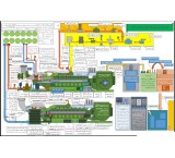
Engineering Documents Required for Construction of CHP, DG, CCHP Power Plants, Distributed Generation, and Small-Scale Generators
This company has the ability to produce all the following documents in full: 1Electrical document ASIC DESIGN - Equipment Data Sheets and Technical Specifications. - P&I diagram for the system. - Calculations for cable sizing according to the Site Conditions. - Power distribution scheme. - Controls, instrumentation, alarms and protection scheme and write up. - Overall key single line Diagram (Detail Design) - MV switchgear single line Diagram - Main LV switchgear single line Diagram - MV switchgear data sheet - LV switchgear data sheet - Main transformer data sheet - Aux transformer data sheet - Generator NGR data sheet - Generator protection&metering&synchronging Single line diagram - Load flow & short circuit study - MV & LV cable list - Battery charger & ups single line Diagram - Battery charger & ups data sheet - MV switchgear logic diagram - LV switchgear logic diagram - Single line diagram of generator metering & protection. - Dimensional layout and sectional drawings for the complete scope of work (including pipe and cable layout). - Schematic and wiring diagram of Battery charger. - Dimensional General Arrangement Drawing of various equipment along with Cross - Section and bill of material. - Layout and mounting arrangement of battery. - Any other drawings/document deemed necessary by the Employer. - Generator curves and characteristics. a) O.C & S.C Characteristics. b) "V" curves. c) Reactive capability curves. d) Generator transient and sub-transient reactance. e) Generator losses, fixed and variables. f) Communication non-interference test curves. g) All other necessary curves for the generator, exciter, AVR and auxiliaries. - Characteristics curves for Pumps and Natural Gas Engines. - Where ever applicable Speed Vs Torque Curve of the pump corresponding to recommended mode of pump starting, superimposed on speed Vs torque curve of the motor corresponding to 80%, 90% and 100% rated voltage. - Selection of D.C. battery and charger rating. - Calculations for net electrical output at site after deducting power consumption of D.G. auxiliaries. - Write-up on specific features of equipment, if any. - Control Philosophy for whole the power plant including Grid interconnection. (SCADA System) - Other Data and Documents required for proper and on time completion of the Contract but not mentioned hereinabove. AFTER AWARD OF CONTRACT AND DURING THE PROJECT ENGINEERING PHASE DETAILED DESIGN - Final version of all data/drawings/schematics/calculations as specified above. - Arrangement of generator phase and neutral terminals. - Wiring diagram of local control panels, D.C. battery charger etc. - Relay setting calculations for generator relays. - Any other drawing/document/data deemed necessary by the Employer. a) Write up on operation, control and monitoring of D.G. plant. b) Cable interconnection diagram and cable schedule. - To be submitted for Approval (A)/Reference (R) and Subsequent Distribution: Transport/shipping dimensions with weights, wheel base detail etc. (R) Terminal arrangements of Generator (A) Rating and Diagram Plate (R) Cable Interconnection Diagram and Cable schedule (R) Drawings of major components like starting system, fuel system, local control panel etc. (A) Detail manufacturing and supply schedule (A) Power distribution scheme (A) Controls, instrumentation, alarms and protection scheme and write up (A) Write up on Voltage regulator and governor (R) Single line diagram of generator metering & protection (A) Preparation of dimensional electrical layout of DG electrical building and sectional views showing disposition of electrical equipment, arrangement of cable trays/ cable rack in cable spreader room and also interconnection with respective DG set and Grid Interconnection. (A) Schematic and wiring diagram of Battery charger (A). Dimensional General Arrangement Drawing of various equipment along with cross - Section and bill of material (A). Layout and mounting arrangement of battery (A). Generator curves and characteristics as mentioned in “Generator curves and characteristics” above. Where ever applicable Speed Vs Torque Curve of the pump corresponding to recommended mode of pump starting, superimposed on speed Vs torque curve of the motor corresponding to 80%, 90% and 100% rated voltage (R). Selection of D.C. battery and charger rating (A). Calculations for net electrical output at site after deducting power consumption of D.G. auxiliaries and for DG sizing. Write-up on specific features of equipment, if any (R). Arrangement of generator phase and neutral terminals (A). Wiring diagram of local control panels, D.C. battery charger etc.(R). Relay setting calculations for generator relays (R). Any other drawing/document/data deemed necessary by the Employer (R). Write up and logic diagram on operation, control and monitoring of D.G. plant (R). Any other relevant drawing or data necessary for satisfactory installation, operation and maintenance (R). Other Data and Documents required for proper and on time completion of the Contract but not mentioned hereinabove. 2 Mechanical document 1. Engine document 1.1. Adjusting, trouble shooting, testing 1.2. Contamination control guidelines 1.3. Disassembly and assembly 1.4. Operation and maintenance manual 1.5. Parts identifications 1.6. schematic 1.7. specifications 1.8. tool operating manual 1.9. torque specifications 2. Gas Engine stack calculation 3. Gas Engine stack arrangement 4. Gas Engine cooling system calculation 5. Gas Engine cooling system p&id 6. Gas Engine cooling system arrangement 7. Gas Engine cooling system arrangement 8. Gas Engine cooling system equipment data sheet 9. Gas Engine cooling system piping plan 10. Gas Engine cooling system piping MTO 11. Gas Engine cooling system piping isometric 12. Gas Engine natural gas piping plan 13. Gas Engine natural gas piping MTO 14. Gas Engine natural gas piping isometric 15. Gas Engine ventilation system calculation 16. Gas Engine ventilation system p&id 17. Gas Engine ventilation system arrangement 18. Gas Engine ventilation system equipment data sheet 19. Gas Engine Mechanical installation details 3 Civil document 1 Civil Design Criteria 2 Structure Design Criteria 3 Drainage Design Criteria 4 Specification For Earth Works 5 Specification For, Storm Sewer And Oily Water Sewer 6 Specification For Fencing & Gates 7 Specification For Gravel Paving 8 Specification For Reinforced Concrete paving 9 Specification For Asphalt Concrete paving 10 Specification For Excavation, Trenching And Backfilling For U-G Utilities 11 Specification For Concrete Works 12 Specification For Fabrication And Erection Of Steel Structures 13 Specification For Base Setting & Grouting Of Equipment 14 Specification For Anchor Bolts 15 Specification for Building 16 Specification for fireproofing 17 Typical Drawing For Fence & Gate 18 Typical Drawing for Anchor Bolts 19 Typical Drawing for Hand Rail 20 Typical Drawing for Ladder 21 Typical Drawing for Stair 22 Typical Access Platform 23 Typical drawing for fireproofing detail 24 Typical drawing for Roads 25 Typical drawing for Oily Water & Domestic Sewer Manhole 26 Typical drawing for Catch Basin 27 Typical drawing for Valve Pit 28 Typical drawing for Cable Trench & Duct Bank 29 Typical drawing for Surface Drainage Ditches 30 Typical drawing for Concret Paving 31 Typical drawing for Underground Crossing 32 Typical Details for Architectural Drawings 33 Topographical Plan 34 Soil Investigation Report 35 Rough Grading Longitudinal & Transverse Profiles 36 Finish Grading and Surface Drainage Plan & Section 37 Electrical &Intrument Cable Trenchs Plan & Section 38 Civil Composite Plot Plan 39 Foundation Location Plan 40 Landscape Plan & Details 41 Drawing for Pipe Supports 42 Calculation Note for Pipe Supports 43 Architectural Drawing for Power House Building 44 Structural Drawing for Power House Building 45 Foundation Drawing for Power House Building 46 Calculation Note for Power House Building 47 Architectural Drawing for Control & Administration Building 48 Structural Drawing for Control & Administration Building 49 Foundation Drawing for Control & Administration Building 50 Calculation Note for Control & Administration Building 51 Architectural Drawing for Workshop and Store Building 52 Structural Drawing for Workshop and Store Building 53 Foundation Drawing for Workshop and Store Building 54 Calculation Note for Workshop and Store Building 55 Architectural Drawing for Switchgear Building 56 Structural Drawing for Switchgear Building 57 Foundation Drawing for Switchgear Building 58 Calculation Note for Switchgear Building 59 Architectural Drawing for Gate Keeper Building 60 Structural Drawing for Gate Keeper Building 61 Foundation Drawing for Gate Keeper Building 62 Calculation Note for Gate Keeper Building 63 Architectural Drawing for Fire water pumps shelter 64 Structural Drawing for Fire water pumps shelter 65 Foundation Drawing for Fire water pumps shelter 66 Calculation Note for Fire water pumps shelter 67 Foundation Drawing for Gas Engine Generator Set and relevant Auxiliaries System 68 Calculation Note for Gas Engine Generator Set and relevant Auxiliaries System Foundation 69 Foundation Drawing for Diesel Generator package 70 Calculation Note for Diesel Generator package Foundation 71 Foundation Drawing for Transformers 72 Foundation Drawing for Fire water pumps 73 Calculation Note for Fire water pumps Foundation 74 Foundation Drawing for Fire Water storage tank 75 Calculation Note for Fire Water storage tank Foundation Foundation Drawing for Other Equipments
Audio and Video Tehran -

BGA IC assembly with
device Automatic and manual electronic board assembly with guaranteed quality as soon as possible with experienced staff and high work experience. BGA IC assembly with BGA Machine. I assembly C BGA, BGA IC disassembly, BGA IC Rebal. Massage of ICs, QFP, TQFP, QFN and .... Assembly of various SMD and DIP components with industrial, medical and .... Perform QC and test assembled electronic boards. Assemble all types of cables and connectors including Circular, Amphenol, SMA, SMB, RG, BNC, etc. Electronic board design, reverse engineering Assembly Module and rack system assembly Supply of original electronic components from the most reputable companies in Europe and China. Order PCB manufacturing from the most reputable companies in China and Taiwan Delivery in the fastest time and with a guarantee Address: Tehran-District 9 Moin Ostad Blvd., Hashemi St. BGA, SMD assembly, PCB assembly, dip board assembly, dip smd board assembly, electronic board assembly, montage ژ dip and smd, assembly of electronic components, assembly of electronic board
Audio and Video Tehran -

Control of the temperature and humidity of the server room
The temperature and humidity control devices of the server room are very numerous in Iran, some manufacturers and others are just the product seller, but what is more important is which system at the cost of it really works and the impression does not happen that it was wrong to buy from the beginning. \r\n\r\n1- If the server intelligent control that is purchased is unstable or gives false warnings\r\n2. If the server room intelligent system is purchased, send a warning late or delayed \r\n3. If the intelligent monitoring of the server room that is purchased is abolished in times of danger and cannot be able to send alerts.\r\n4. If the intelligent controller the server room temperature is purchased does not have the quality needed to protect the server room\r\n5. If the intelligent automation of the server room is purchased is provided by a company that has little experience in control and automation.\r\n6. If the intelligent control of the server room is not interior design and we have to spend a lot of time repaired \r\n\r\n[Types of Server Room Sensors] (https://pishrans.com/%25d9%2585%25d9%2582%25d8%25A7%2584%25d8%25A7%25d8%25aaa/174-sever-room-sensorsors)\r\nThe above and other things can cause irreparable problems for the server room manager, so the employer ultimately concludes that the choice is made, but this choice is no longer reversible and cannot offset the damage to the server room or the server room data and cannot retrieve the intelligent control system.\r\nTherefore, the solution to these events is to scrutinize and select the correct and secure intelligent system.\r\n \r\nhttps://pishrans.com/src2-2\r\nResume \r\nhttps://pishrans.com/projects1\r\nPhoto of projects\r\nhttps://pishrans.com/photo-project
Audio and Video Tehran -
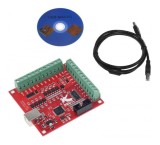
Four-axis USB Mach3 controller board with 100KHZ output pulse
The four-axis CNC controller board uses powerful MACH3 software and can control a maximum of 4 stepper motors simultaneously. The wrist CNC controller board uses a USB port. Suitable for connecting to laptops and new systems Mach3 controller is a PC Base based controller and has all the features that a powerful controller needs. 4-axis wrist CNC controller board to build a router CNC, laser router, etc. Areas of application The four-axis wrist CNC controller board is suitable for all types of small and medium automation equipment and equipments, such as engraving machine, strip machine, marking machine, cutting machine, laser machine, Medical equipment, CNC machine tools, automatic assembly equipment, electronic processing equipment ... Support for 3-axis or 4-axis connection, you can connect four stepper motor drivers or servo drivers Maximum stepping pulse frequency 100 kHz, which is suitable for servo motor or stepper motor Water support Automatic probe field Emergency input support Limit switch support (or 3-wire PNP Proximity switch) Electronic cart connection support To separate USB and external port and stabilize the system, you must Use 24V DC external power supply. It has an output port of 0-10V, you can use mach3 software to control the speed of the spindle motor. 4 General purpose input, you can use limited switch, stop switch, Connect the probe switch, return to zero and other devices. 4 All-purpose isolated relay drive output interface, can have four relays to control spindle start, forward rotation and reverse rotation, pumps and other devices Drive slowly. 1 The status LED shows the connection status on the board. Technical specifications: External voltage: 24/12 volts Operating frequency: 100KHz Support: 4-axis The maximum phase pulse is 100 kHz, which is suitable for motors and servo motors From probe tools Automatically supports Exit port for spindle control 0-10V has emergency input "0102 030405 "Controller board, CNC controller board, CNC controller board, four-axis controller board, MACH controller board, four-axis CNC controller board" 0102030405 "
Audio and Video East Azarbaijan
Similar Products
-