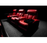
Sale of XGSLAB10 with CYMEGRD8 and CDEGS - Sale of CYMEGRD8 and CDEGS17 and DIGSILENT2024 and DEHN CYMCAP ETAP2024 without limitation and with any number of users you want.
If you wish to purchase CYMGRD8 or CYMCAP or CDEGS or PLSCADD or CDEGS 17 and DEHN SUPPORT or DIGSILENT 2024 ETAP2024 or XGSLAB or PVSYST 8.06, contact 09126717215. In this post, a free download link for CYMGRD 6.3 is provided for engineers and students.
This company performs all grounding system calculations with CymeGRD8, ETAP2024, CDEGS, and XGSLAB software.
CYMGRD is software for designing and analyzing grounding systems, created to assist engineers in optimizing new network designs and reinforcing existing networks (of any shape). Advanced features in the software's graphical environment along with efficient analysis algorithms make this software a powerful tool that helps engineers create technically and economically sound designs.
If you wish to purchase CYMGRD8 or CDEGS17 or ETAP 20, contact 09126717215.
The term CDEGS, which stands for Current Distribution, Electromagnetic Fields, Grounding and Soil Structure Analysis, is a powerful integrated software suite designed by sestech for precise analysis of various electromagnetic problems occurring in all industries including electrical networks. Among these, only the SES (Safe Engineering Services & Technologies Ltd) software professionally addresses grounding system design. Some unique capabilities of this software compared to others include:
High-frequency grounding system design
Optimal grounding system design for substations and power plants compared to other software
Grounding system design in soil with any number of layers (horizontal, vertical, spherical, cylindrical, with defined volume, etc.), used for special centers like dams
Fault current distribution analysis in grounding networks
Studies of lightning strike scenarios to transmission lines, telecom towers, wind turbines, nuclear power plants, etc.
Analysis of transmission and distribution line parameters, power cables, EMI and EMC
Optimal 3D lightning protection system design (lines, substations, etc.) according to IEEE and IEC standards
Analysis of electromagnetic problems caused by transmission lines on adjacent facilities like railways, oil and gas pipelines, etc.
Assessment of electromagnetic effects on the environment (corona, acoustic noise, radio noise)
The SES software suite from Canada includes several software packages, with the CDEGS package being the most prominent.
The CDEGS software package consists of 8 modules: RESAP, MALT, MALZ, TRALIN, SPLITS, HIFREQ, FCDIST, FFTSES, or 12 software packages including AutoGround, MultiGround, MultiGround+, MultiGroundZ, MultiGroundZ+, MultiFields, MultiFields+, MultiFieldsPro, MultilLines, AutoGridPro, AutoGroundDesign, Right-Of-Way.
CDEGS offers advanced solvers for the mentioned problems:
Direct solutions of Maxwell's equations
Circuit-based analyses
Finite element methods
Inversion algorithms
Fourier analysis (FFT)
Transient analysis
Hybrid methods
It covers all electromagnetic coupling modes:
Conduction through metallic elements, coatings, and soil
Magnetic induction
Capacitive effects
CDEGS includes the following cores:
RESAP: Soil Resistivity Analysis
MALT: Low Frequency Grounding/Earthing Analysis
TRALIN: Detailed Fault Current Distribution and EMI Analysis
HIFREQ: Electromagnetic Fields Analysis
FCDIST: Simplified Fault Current Distribution Analysis
MALZ: Frequency Domain Grounding/Earthing Analysis
SPLITS: Detailed Fault Current Distribution and EMI Analysis
FFTSES: Automated Fast Fourier Transform Analysis
Supporting tools include Autotransient, CETU, FFT21Data, GraRep, GRServer, GRSplits, GRSplits-3D, ROWCAD, SESAmpacity, SESBat, SESCAD, SESConductorDatabase, SESConverter, SESCrossSection, SESCurveFit, SESeBundle, SESEnviroPlot, SESFcdist, SESFFT, SESGSE, SESImpedance, SESLibrary, SESPlot, SESPlotViewer, SESResap, SESResultViewer, SESScript, SESShield, SESSystemViewer, SESThreshold, SESTralin, SICLCommand, SoilModelEditor.
Each software package consists of a combination of several modules as detailed in the table.
This software enables the design of grounding for substations, power plants, factories, and buildings. The design can be for uniform or two-layer horizontal soils and calculates touch and step voltages according to IEEE standards.
For grounding system calculations of solar power plants, considering that panel structures are part of the grounding system, calculations differ somewhat from typical substation grounding.
This software receives fault current magnitude and duration, soil thickness, soil resistivity, and body weight from the user and performs the following operations using soil, network, and diagram modules:
Soil Module
Measures soil resistivity based on one or two-layer models. This module can plot measured and calculated resistivity and compute maximum virtual touch and step voltages according to standards.
Network Module
Calculates current released by each conductor into the soil and determines soil surface potential using these currents. The grounding network can be defined as a single conductor or a set of conductors connected in a square. Substation layout can be drawn in 2D or 3D. Underground pipes and adjacent grounding networks can also be considered to see their impact on fault current and surface voltage.
Diagram Module
Summarizes soil resistivity and surface potential analysis results on the display and uses 2D and 3D colored shapes for better presentation.
Key features of CYMGRD software:
Grounding system design for low frequencies (especially substation grounding design according to IEEE 80-2000)
Support for IEEE 80 2000, IEEE 81 1983, and IEEE 837 2002 standards
Finite element analysis of conductors and rods in grounding networks
Calculation of station ground resistance (Rg) and Ground Potential Rise (GPR)
Touch and surface potential analysis inside and outside the network with color display
Step voltage analysis
Support for symmetrical or asymmetrical networks of any shape
Modeling of return electrodes and distinct electrodes
Calculation of maximum single-phase to ground current for a specified network
...
CYMGRD Screenshot 1 CYMGRD Screenshot 2
CYMGRD software is a substation grounding grid design and analysis program specially developed to help engineers optimize new grids and reinforce existing grids of any shape, featuring easy-to-use built-in danger point evaluation tools. User-friendly data entry, efficient analysis algorithms, and powerful graphical tools make CYMGRD an effective tool for technically sound and economical designs.
Program Features
CYMGRD allows rapid analysis of various design alternatives to choose economical solutions for any installation.
The program complies with IEEE 80™ 2000, IEEE 81™ 1983, and IEEE 837™ 2002.
Analytical Capabilities
Finite element analysis of ground grid conductors and rods
Computation of station ground resistance (Rg) and Ground Potential Rise (GPR)
Touch and surface potential analysis inside and outside grid perimeter with 2D or 3D color display
Step voltage analysis
Uniform or two-layer soil model from field measurements or user-defined values
Computation of reduction factor (Cs)
Library of common surface layer materials
Library of typical station soil resistivity values
Safety assessment for maximum permissible touch and step voltages per IEEE 80™ 2000
Current Split Factor (SF) estimated from substation configuration per IEEE 80™ 2000
Decrement Factor (DF) from bus (X/R) ratio and shock duration per IEEE 80™ 2000
DC component of asymmetrical fault current included
Electrode analysis for optimal sizing of conductors and rods per IEEE Std. 80-2000 and Std. 837-2002
Supports symmetrical or asymmetrical grids of any shape
Arbitrarily located ground rods
Modeling of return and distinct electrodes
Modeling of concrete-encased rods
Computation of maximum single-phase to ground fault current
The CYMGRD/AutoCAD® Interface module
Allows switching between AutoCAD® and CYMGRD environments.
This utility is not a substitute for AutoCAD®, which remains required to produce .DXF or .DWG files containing the substation grid layout.
Simulation Results Management
Chart features include:
Graphical comparison of soil model with field measurements
Color-coded surface potential gradients based on thresholds
Equipotential contours in 2D or 3D with adjustable viewing angles
Graphs of touch and step voltage variations along lines compared to safety values
Graphic indication of analyzed areas on 2D grid layout
More info (open/close)
DEHN Earthing Tool software calculates the required length of grounding electrodes according to IEC 62305-3 standard based on electrode types A and B and foundation electrodes. Soil resistivity is a key factor in determining electrode length. To purchase DEHN, call 09126717215.
Training Topics:
◄ Necessity of grounding system
◄ Soil characterization
◄ Conductors and Rods tabs
◄ Settings for grounding system calculation
◄ Performing grounding system calculations
◄ Optimizing number of conductors and rods
◄ FEM method review
◄ IEEE method review
Grounding design with GSD: An online software for static grounding system calculations providing step-by-step simple design for electrical engineers. Calculation methods are based on formulas and relations recommended in BS 7430 and IEEE80 standards. Results are acceptable for engineering design; for more precise design, Tesla’s GLE software, approved by Amirkabir University, is recommended.
Software features include:
Register design and receive a dedicated user panel
Short circuit calculation in TN and TT networks considering distribution factors, X/R ratio, and other IEEE80 recommendations
Interpretation of soil resistivity in multilayer soils and determination of apparent resistivity and effective depth
Grounding system calculations including resistance, GPR graph, step voltage, touch voltage, protective device trip time, and selection of trip curves and devices
Selection of electrode and conductor materials
Preparation of official report in PDF format
Tested download link for CYMGRD V.6.3.R7:
https://s25.picofile.com/file/8455555850/CYMGRD_V_6_3_R7.rar.html
Password: cyme
Installation method:
First disable antivirus, then run grd637 file. After installation, place pk42mvdR.dll in the software installation folder (usually not in C drive). Then click CYMGRD inside the installation folder to run the software. If no error appears, installation is successful. If an error about missing SC32W file appears, copy contents of REQUIRED FILE folder into the installation folder to fix the issue.
Training for latest version CYMCAP 8.0 Rev2
Calculating appropriate cable size in various projects is one of the most important engineering tasks, often done manually. If the selected size is smaller than needed, cable damage or system malfunction may occur; if larger than necessary, despite proper function, economic design is compromised. Designers usually calculate cable size based on voltage drop and short circuit criteria, neglecting thermal sizing. For thermal sizing, especially in MV and HV cables, cable construction and layer specifications must be precisely modeled, and allowable current calculated based on installation environment such as underground, air, tunnels, ducts, trenches, etc. This course uses the professional cable sizing software CYMCAP to familiarize you with cable aspects, steady-state sizing, transient sizing based on current profile, estimation of temperature field around cables, calculation of magnetic flux density, induced voltage on shield, optimizing cable arrangement in duct banks, cable impedance matrix calculation, etc., based on IEC60853, IEC 60287, and Neher-McGrath methods.
Tehran